Collect, compute, and visualize key production and technical metrics of the enterprise
Main features:
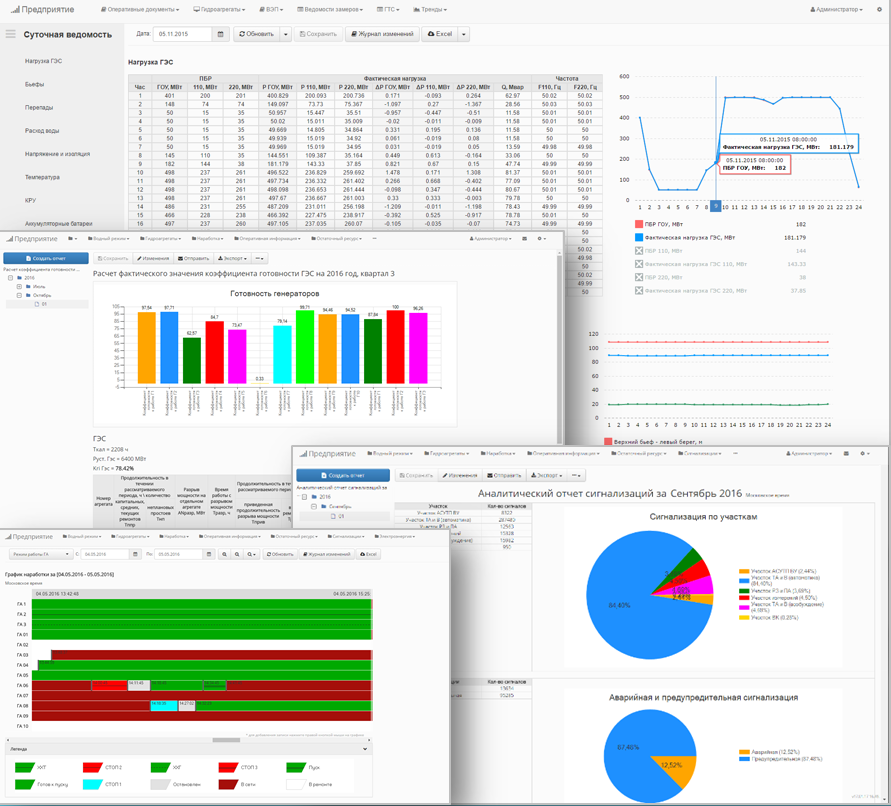
- Creation of all types of reports - from daily statements and plan/fact reports to equipment runtime and production efficiency reports.
- Calculation of material and energy balances.
- Collection of data from heterogeneous systems of APCS / MES / ERP / DBMS.
- Real-time report generation.
- Secure access to reports for all enterprise employees according to their permissions.
- Deployment options: as a stadalone web application or as a WinCC OA module.
Features
A set of built-in modules allows you to collect data from various enterprise systems, perform the necessary calculations and provide information both for the visualization of the production process and for decision making.
Reporting
The reporting module provides capabilities for creating and maintaining a long-term database of reporting documentation. A visual report form designer is used to create new templates, which allows you to create reports of any complexity. Reports can be generated both on schedule and on event.
More details
Integration
TechnoDoc drivers can connect to enterprise systems using common industrial protocols (OPC UA/DA/HDA), databases (PostgreSQL, SQL Server, Oracle, InfluxDB), and can gather data from text files (TXT, CSV, Excel) as well as from information systems via a provided API.
More details
Equipment operating time
The module automates the process of accounting for equipment operating time in various modes, as well as accounting for the number of equipment on/off cycles. Based on the module's data, OEE, MTTR, MTBF indicators are calculated.
More details
Enterprise model description
The Common Information Model (CIM) methodology is used to describe the enterprise's reference and regulatory information. This solution allows maintaining arbitrary structure and nested reference data. Using the profile editor, you can build various hierarchical representations of directories.
More details
Industrial solutions
TechnoDoc can be used to solve a variety of common industrial tasks, such as residual resource calculation, equipment operation time calculation in limited zones, allowable and actual energy imbalance calculation, material balance calculation, water flow calculation and forecasting through the hydrosystem, and the formation of summaries for emergency events.
More details
Deployment options
TechnoDoc can be installed as a standalone web application or as a module of WinCC OA. For storing service data, TechnoDoc can use any of the following DBMS: PostgreSQL, MS SQL Server, MariaDB, or SQLite.
More details
Projects
The SMS Automation group has developed and implemented solutions for managing production reports at various industrial enterprises.